Thin Film Evaporator, System ETF

The Thin Film Evaporator system ETF is used for gentle partial evaporation of liquid mixtures, especially when requirements – e.g. high viscosities or very short residence times – exceed the possibilities of classical evaporators or of the falling film evaporator system EFF.
The raw solution is fed from a feed batch tank or continuously into the evaporator. A wiper system distributes it evenly around the circumference as a thin film. The low boilers are then partially evaporated from the film flowing down and constantly redistributed on the evaporator surface by the wiper system, condense as distillate on the external condenser and flow off from there. Similarly, the concentrate exits the evaporator along the heated wall. The distillate and concentrate are either collected in a receiver tank or continuously discharged by a pump.
Vacuum pumps are used to set the desired process conditions such as pressure and temperature. Thermostats (laboratory and pilot scale) are used for heating, evaporation and condensation. On a production scale, classic energy sources such as steam, thermal oil respectively cooling water, brine and glycol are used. A cold trap is used to reduce the undesired entry of low boilers from the exhaust gas flow into the vacuum pump system.
- Evaporators with low hold-up and corresponding short residence time with narrow residence time distribution and gentle operating conditions for
- Laboratory and pilot systems made of stainless steel with borosilicate glass 3.3 in standardized design, optional process-specific adaptations
- Production systems made of stainless steel in process- and customer-specific design
- Modular supplementary evaporator systems according to process requirements, e.g.
- Upstream and downstream evaporators, e.g. EFF-ETF system, or Flash-Box
- Rectification column for concentration of the vapours, system ETR
- Process and customer-specific guidelines, e.g. ATEX, DGRL, FDA, GAMP, ASME, UL standards.
- Suitable for media with increased demands:
- Viscous and highly viscous media
- Foaming media
- Heat-sensitive media
- Solids-containing media
- Higher-melting media
- Feasibility studies or existing expertise for typical applications
- Fatty acids and fatty acid derivatives
- By-products from the production of edible oil
- Special polymers or oligomers
- Pharmaceutical and cosmetic products
- Specialty chemicals
- Fragrances and flavourings
Test distillation and laboratory / pilot evaporator system
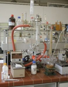 In addition to the composition of the distillate and/or residue or group of residues, product properties such as smell and colour are also relevant for many applications. Likewise, possible effects that may occur during evaporation, such as foaming or fouling on the heat transfer surface, must be taken into account. The latter cannot be determined or estimated theoretically, but require the possibility of a visual evaluation of the evaporation process. This can best be implemented in glass plants from COROSYS, which can be individually assembled on the basis of a modular system.
Once the basic feasibility has been established, the process parameters for the design of a production plant shall be verified, i.e. heat transfer and maximum area-related evaporation rates or applicatory number of stages as well as the achievable yields and qualities shall be determined. For this purpose, COROSYS has a standardized series of pilot plants made of stainless steel (optionally also special materials) in various sizes and designs to choose from.
For new evaporation or distillation tasks, COROSYS offers in-house services ranging from literature research, thermodynamic simulations and laboratory tests to piloting of single systems or combinations of falling film (EFF), thin film (ETF) and short path evaporators (ESF), if necessary also in combination with rectification (ERF).
The main objectives and possibilities of preliminary studies/test distillations as well as laboratory and pilot plants are summarized in the following table:
| Pre-studies / Test distillations | Laboratory systems | Pilot systems | |
|---|---|---|---|
| Literature/Patent research, determination of substance data, themodynamic modelling of evaporation/rectification | Feasibility check | Detailed process data determination based on feasibility study and preselected evaporator system | |
| Stainless steel with borosilicate glass 3.3 | Stainless steel with borosilicate glass 3.3, optionally other materials | Stainless steel, optionally other materials | |
| Tests to determine feasibility / selectivity | Laboratory tests mostly with a pre-selected film evaporator system | Engineering of the production plant with dimensioning of apparatuses and media | |
| Comparison of the different film evaporator systems and subsequent pre-selection | Determination of the straightening process parameters and achievable yields and qualities | Detailed determination of process parameters and achievable yields and qualities | |
| Visual evaluation of system behaviour (colour, smell, foam, solids, deposits, …) | Consideration and visual evaluation of the system behaviour (colour, smell, foam, solids, …) | Consideration of the system behaviour (colour, smell, foam, solids, deposits, …) | |
| Coordination of the analytics | Sample quantities or very small production quantities | Larger sample quantities or small production quantities |
Standard modules and options
Thin Film Evaporators for laboratory and pilot applications can be assembled from numerous modules and options listed in the table below. For a detailed characterization with process requirements, the questionnaire for evaporator processes is available as a supplement.
Technical specification of industrial evaporators
| Area | Evaporator | Exchange surface | Diameter | Heated length | Material | Feed |
|---|---|---|---|---|---|---|
| [m²] | [DN] | [mm] | [kg/h] | |||
| Laboratory | ETF 0002-G | 0,02 m² | DN 40 | 160 | Stainless steel / borosilicate glass 3.3 | 0,03 – 0,6 |
| Laboratory | ETF 0006-G | 0,06 m² | DN 80 | 240 | Stainless steel / borosilicate glass 3.3 | 0,2 – 1,5 |
| Pilot | ETF 0006-S | 0,06 m² | DN 80 | 240 | Stainless steel | 0,2 – 6,0 |
| Pilot | ETF 0012-S | 0,12 m² | DN 125 | 310 | Stainless steel | 1,0 – 12 |
| Pilot | ETF 0030-S | 0,3 m² | DN 200 | 480 | Stainless steel | 2,0 – 30 |
| Pilot | ETF 0060-S | 0,6 m² | DN 250 | 760 | Stainless steel | 2,5 – 60 |
| Pilot | ETF 0120-S | 1,2 m² | DN 300 | 1.270 | Stainless steel | 5 – 120 |
| Area | Option |
|---|---|
| Directives |
|
| Material |
|
| Feed |
|
| Evaporator |
|
| Vacuum system |
|
| Cold trap |
|
| Discharge of concentrate & distillate |
|
| Temperature control |
|
| Other |
|
1) T = Thermostat S= Steam E=Electrical C= Cooling Media CW=Cooling Water
Production-scale evaporator systems
 P
P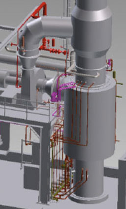 roduction plants are usually designed for specific processes, usually on the basis of pilot tests. Typical evaporation capacities of industrial ETF evaporators start from a few kilograms up to several tons per hour. Depending on the product and task, different wiper systems are available.
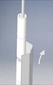
The wiper systems are overhung, optionally equipped with dynamic droplet separators as well as a double-acting mechanical seal to protect the wiper basket shaft from the atmosphere. In principle, fine machining of the surfaces in contact with product and the use of alternative materials are also possible.
The production plants are preferably designed as package units, which on the one hand reduces the customers’ planning effort and on the other hand especially the time required for installation and commissioning on site at the customer.
The construction of the production systems is carried out in compliance with the necessary directives such as DGRL 2014/68 EU or ASME, ATEX 2014/34 EU, UL standards, GMP guidelines, TA-Luft and the machinery directive 2006/42/EG.
Technical specification laboratory and pilot evaporators
| Area | Evaporator | Exchange surface | Diamter | Heated Length | Total LengtH | Material |
|---|---|---|---|---|---|---|
| [m²] | [DN] | [mm] | [mm] | |||
| Industry | ETF 0120-S | 1,2 m² | DN 300 | 1.270 | 2.800 | Stainless steel |
| Industry | ETF 0200-S | 2,0 m² | DN 400 | 1.590 | 3.385 | Stainless steel |
| Industry | ETF 0400-S | 4,0 m² | DN 700 | 1.820 | 4.130 | Stainless steel |
| Industry | ETF 0600-S | 6,0 m² | DN 700 | 2.730 | 5.040 | Stainless steel |
| Industry | ETF 0900-S | 9,0 m² | DN 1000 | 2.870 | 5.685 | Stainless steel |
| Industry | ETF 1200-S | 12,0 m² | DN 1000 | 3.820 | 6.640 | Stainless steel |
Larger evaporators are available on request.

