Centrifugal Evaporator, System ECF

The centrifugal evaporator system ECF is used for gentle partial evaporation of liquid mixtures, especially when requirements – e.g. high viscosities or very short residence times – exceed the capabilities of classical evaporators including the falling film and thin film evaporator systems EFF and ETF and even the short path evaporator system ESF.
The raw solution is fed from a feed batch tank or continuously into the evaporator and distributed by the centrifugal effect as a very thin film over the surface of the evaporator for a very short residence time. The low boilers are partially evaporated by the evaporator surface, the temperature difference can be kept very narrow due to the particularly high heat transfer coefficients. The distillate condenses at the internal condenser and flows from there either into a receiver or is continuously discharged by a pump. Similarly, the concentrate flows out of the evaporator through the pressure built up by the centrifugal effect – without an additional pump.
Vacuum pumps are used to set the desired process conditions such as pressure and temperature, and thermostats (laboratory and pilot scale) are used for heating, evaporation and condensation. On a production scale, classic energy sources such as steam, thermal oil or cooling water, cooling brine and glycol are used. A cold trap is used to reduce the undesired entry of low boilers from the exhaust gas flow into the vacuum pump system.
- Evaporators with low hold-up and corresponding short residence time with narrow residence time distribution and gentle operating conditions for
- Laboratory and pilot systems made of stainless steel with borosilicate glass 3.3 in standardized design, optional process-specific adaptations
- Production systems made of stainless steel in process- and customer-specific design
- Modular supplementary evaporator systems according to process requirements, e.g.
- Upstream and downstream evaporators, e.g. EFF-ETF system
- Flash-Box
- Process-specific and customer-specific conditions, e.g. ATEX, PED, FDA, GMP, ASME, UL standards.
- Suitable for media with increased demands:
- Heat-sensitive media
- Solids-containing media
- Higher-melting media
- Feasibility studies or existing expertise for typical applications
- Fatty acids and fatty acid derivatives
- By-products from the production of edible oil
- Special polymers or oligomers
- Pharmaceutical and cosmetic products
- Specialty chemicals
- Fragrances and flavourings
Labororatory / Pilot evaporator systems and preliminary tests
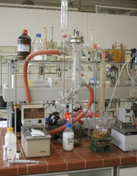
For many applications, in addition to the composition of distillate and/or residue or concentrate, product properties such as odour and colour are also relevant. Likewise, possible effects that may occur during evaporation, such as foaming or fouling on the heat transfer surface, must be taken into account. The latter cannot be determined or estimated theoretically, but require the capability of a visual evaluation of the evaporation process. This can best be implemented in glass plants from COROSYS, which can be individually assembled in a modular system.
Once the general feasibility has been established, the process parameters for the design of a production plant shall be verified, i.e. heat transfer and maximum area-related evaporation rates or practical number of stages as well as the achievable yields and qualities shall be determined. For this purpose, COROSYS has a standardized series of pilot plants made of stainless steel (optionally also special materials) in various sizes and designs to choose from.
For new evaporation or distillation tasks, COROSYS offers in-house services ranging from literature research, thermodynamic simulations and laboratory tests to piloting of single systems or combinations of falling film (EFF), thin film (ETF), short path (ESF) and centrifugal evaporators (ECF), if necessary also in combination with rectification (ERC).
The main objectives and possibilities of preliminary studies/test distillations as well as laboratory and pilot plants are again briefly and clearly summarized in the following table:
| Pre-studies / Test distillations | Laboratory systems | Pilot systems | |
|---|---|---|---|
| Literature/Patent research, determination of substance data, themodynamic modelling of evaporation/rectification | Feasibility check | Detailed process data determination based on feasibility study and preselected evaporator system | |
| Stainless steel with borosilicate glass 3.3 | Stainless steel with borosilicate glass 3.3, optionally other materials | Stainless steel, optionally other materials | |
| Tests to determine feasibility / selectivity | Laboratory tests mostly with a pre-selected film evaporator system | Engineering of the production plant with dimensioning of apparatuses and media | |
| Comparison of the different film evaporator systems and subsequent pre-selection | Determination of the straightening process parameters and achievable yields and qualities | Detailed determination of process parameters and achievable yields and qualities | |
| Visual evaluation of system behaviour (colour, smell, foam, solids, deposits, …) | Consideration and visual evaluation of the system behaviour (colour, smell, foam, solids, …) | Consideration of the system behaviour (colour, smell, foam, solids, deposits, …) | |
| Coordination of the analytics | Sample quantities or very small production quantities | Larger sample quantities or small production quantities |
Standard systems and options for laboratory and pilot systems
Centrifugal evaporators for laboratory and pilot applications can be assembled from numerous modules and options. The following table is intended to show the possibilities and thus support the concept development. For a detailed characterization with process requirements, our questionnaire for evaporator processes is also available.
Technical specification of laboratory and pilot evaporators
| Area | Evaporator | Exchange surface | Diameter | Condensator exchange surface | Material | Feed dimensions |
|---|---|---|---|---|---|---|
| [m²] | [DN] | [mm] | [kg/h] | |||
| Lab | ETF 0004-G | 0,04 m² | DN 150 | 0,1 m² | Stainless Steel / Boro 3.3 | 1 – 15 |
| Pilot | ETF 0012-G | 0,12 m² | DN 250 | 0,3 m² | Stainless Steel / Boro 3.3 | 7 – 70 |
| Area | Option |
|---|---|
| Directives |
|
| Material |
|
| Feed |
|
| Evaporator |
|
| Vacuum system |
|
| Cold trap |
|
| Discharge of concentrate & distillate |
|
| Temperature control 1) |
|
| Other |
|
1) T = Thermostat S= Steam E=Electrical C= Cooling Media CW=Cooling Water
Productions-scale evaporator systems
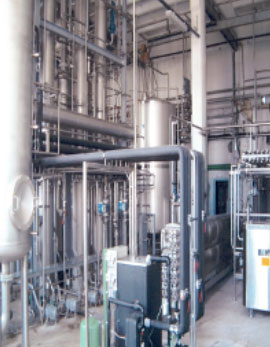
Production plants are usually dimensioned for specific processes, usually on the basis of pilot tests. Typical evaporation capacities of industrial ECF evaporators start from a few kilograms up to several tons per hour. Depending on the product and task, different wiper systems are available. The wiper systems are overhung, optionally equipped with dynamic droplet separators as well as with double-acting mechanical seals to seal the wiper basket shaft against the atmosphere. In principle, fine machining of the surfaces in contact with the product and the use of alternative materials are also possible.
The production plants are preferably designed as package units, which on the one hand reduces the customers’ planning effort and on the other hand especially the time required for installation and commissioning on site at the customer.
The construction of the production systems is carried out in compliance with the necessary directives such as PED 2014/68 EU or ASME, ATEX 2014/34 EU, UL standards, GMP guidelines, TA-Luft and the machinery directive 2006/42/EG.
Technical speficifation of industrial evaporators
| Area | Evaporator | Exchange surface | Diameter | Exchange surface condensator | Material | Feed dimensions |
|---|---|---|---|---|---|---|
| [m²] | [DN] | [m²] | [kg/h] | |||
| Industrial | ETF 0030-S | 0,3 m2 | DN 400 | 1,0 m2 | Stainless Steel | 20 – 200 |
| Industrial | ETF 0075-S | 0,3 m2 | DN 600 | 2,0 m2 | Stainless Steel | 40 – 400 |
| Industrial | ETF 0150-S | 4,0 m² | DN 800 | 5,0 m2 | Stainless Steel | 75 – 750 |
| Industrial | ETF 0300-S | 6,0 m² | DN 1200 | 8,0 m2 | Stainless Steel | 120 – 1.200 |

