Falling film evaporator, System EFF

The falling film evaporator system EFF is used for gentle partial evaporation of liquid mixtures, especially when requirements – e.g. low operating pressures at high evaporation rates – exceed the capabilities of classical evaporators.
The raw solution is fed into the evaporator from a feed batch vessel or continuously and evenly distributed as a thin film over the surface of the evaporator tubes with a special distribution system. The low boilers are partially evaporated from the descending film, flow with the concentrate into the sump of the falling film evaporator and are conducted as steam to the external condenser for condensation. As a result, the distillate flows out of the condenser.
Meanwhile, the non-evaporated liquid flows along the falling film evaporator tubes, is continuously concentrated by the evaporation and finally flows as concentrate into the evaporator sump and from there out of the evaporator. Concentrate and distillate are either collected in a receiver or continuously discharged via a pump.
Vacuum pumps are used to set the desired process conditions such as pressure and temperature, and thermostats (laboratory and pilot scale) are used for heating, evaporation and condensation. On a production scale, classic energy sources such as steam, thermal oil or cooling water, cooling brine and glycol are used. A cold trap is used to reduce the undesired entry of low boilers from the exhaust gas flow into the vacuum pump system.
- Compact evaporation devices and systems with low hold-up and correspondingly short residence time with narrow distribution and gentle operating conditions
- Laboratory and pilot systems made of stainless steel and borosilicate glass 3.3 in standardized modular design, optional process- and customer-specific adaptations
- Production systems made of stainless steel in process- and customer-specific design
- Modular supplementary evaporator systems according to process requirements, e.g.
- Downstream evaporators, e.g. system ETF-ESF
- Vapour rectification column, EFR system
- Process-specific and customer-specific conditions, e.g. ATEX, DGRL, FDA, GAMP, ASME, UL standards
- Suitable for media with increased demands:
- Low-viscosity media
- Heat-sensitive media
- Solids-containing media
- Larger feed quantities, especially with a high low-boiling component
- Existing expertise for typical applications or feasibility studies with tests and scale-up verification
- Food, e.g. coffee and dairy products, but also vitamins
- Flavours and fragrances
- Fatty acids
- Process wastewater
- Various other products of the fine chemicals and pharmaceuticals sector
Laboratory and pilot evaporator systems and prelminiary test
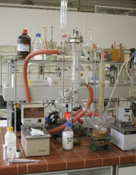
For many applications, in addition to the composition of distillate and/or residue or concentrate, product properties such as odour and colour are also relevant. Likewise, possible effects that may occur during evaporation, such as foaming or fouling on the heat transfer surface, must be taken into account. The latter cannot be determined or estimated theoretically, but require a visual evaluation of the evaporation process. This can best be implemented in glass plants from COROSYS, which can be individually assembled in a modular system.
Once the general feasibility has been established, the process parameters for the design of a production plant shall be verified, i.e. heat transfer and maximum area-related evaporation rates or practical number of stages as well as the achievable yields and qualities shall be determined. For this purpose, COROSYS has a standardized series of pilot plants made of stainless steel (optionally also special materials) in various sizes and designs to choose from.
For new evaporation or distillation tasks, COROSYS offers in-house services ranging from literature research, thermodynamic simulations and laboratory tests to piloting of single systems or combinations of falling film (EFF), thin film (ETF) and short path evaporators (ESF), if necessary also in combination with rectification (ERF).
The main objectives and possibilities of preliminary studies/test distillations as well as laboratory and pilot plants are again briefly and clearly summarized in the following table:
| Pre-studies / Test distillations | Laboratory Systems | Pilot systems | |
|---|---|---|---|
| Literature/Patent research, determination of substance data, themodynamic modelling of evaporation/rectification | Feasibility check | Detailed process data determination based on feasibility study and preselected evaporator system | |
| Stainless steel with borosilicate glass 3.3 | Stainless steel with borosilicate glass 3.3, optionally other materials |
Stainless steel, optionally other materials |
|
| Tests to determine feasibility / selectivity | Laboratory tests mostly with a pre-selected film evaporator system | Engineering of the production plant with dimensioning of apparatuses and media | |
| Comparison of the different film evaporator systems and subsequent pre-selection | Determination of the straightening process parameters and achievable yields and qualities | Detailed determination of process parameters and achievable yields and qualities | |
| Visual evaluation of system behaviour (colour, smell, foam, solids, deposits, …) | Consideration and visual evaluation of the system behaviour (colour, odour, foam, solids, …) | Consideration of the system behaviour (colour, odour, foam, solids, deposits, …) | |
| Coordination of the analytics | Sample quantities or very small production quantities | Larger sample quantities or small production quantities |
Standard systems and options for laboratory and pilot systems
Short Path Evaporators for laboratory and pilot applications can be assembled from numerous modules and options listed in the table below. For a detailed characterization with process requirements, the questionnaire for evaporator processes is available as a supplement.
Technical specifications of laboratory and pilot evaporators
| Area | Evaporator | Exchange surface | Diameter | Heated length | Material | Feed dimensions |
|---|---|---|---|---|---|---|
| [m²] | [DN] | [mm] | [kg/h] | |||
| Lab | EFF 0008-G | 0,08 m² | DN 25 | ca. 1.000 | Stainless Steel/ Borosilicate Glass 3.3 | 0,5 – 6 |
| Lab | EFF 0025-G | 0,25 m² | DN 50 | ca. 1.500 | Stainless Steel/ Borosilicate Glass 3.3 | 1 – 12 |
| Lab | EFF 0040-G | 0,4 m² | DN 80 | ca. 1.500 | Stainless Steel/ Borosilicate Glass 3.3 | 1,5 – 18 |
| Pilot / Small batch | EFF 0100-S | 1,0 m² | DN 125 | ca. 1.500 | Stainless Steel | 7 – 60 |
| Pilot / Small batch | EFF 0300-S | 3,0 m² | DN 200 | ca. 1.800 | Stainless Steel | 20 – 200 |
| Pilot / Small batch | EFF 0600-S | 6,0 m² | DN 250 | ca. 2.200 | Stainless Steel | 30 – 350 |
In addition, there are numerous available options listed below. The options do not represent a complete characterization, but are intended to show the possibilities for the customer and to support the efficient development of a concept for feasibility, as far as the characterization is not done by the questionnaire for evaporation processes.
Options for Falling Film Evaporator EFF
| Area | Option |
|---|---|
| Directives |
|
| Material |
|
| Feed |
|
| Evaporator |
|
| Vacuum system |
|
| Cold trap |
|
| Discharge concentrate & distillate |
|
| Temperature control1) |
|
| Other |
|
1) T = Thermostat S= Steam E=Electrical C= Cooling Media CW=Cooling Water
Production-scale evaporator systems
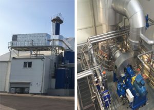 For many known applications and also numerous new processes, which have been dimensioned in advance through studies and tests, evaporator systems are realized on a production scale. The production plants are preferably designed as package units, this reduces the planning effort on the one hand and, in particular, the installation and commissioning time on site at the customer’s premises on the other.
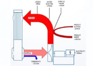
The evaporator systems on a production scale are individually dimensioned for the customer processes. The typical and most common evaporator sizes range from 2.5 m² to over 4,000 m². For larger plants, attempts are made to integrate a heat recovery system suitable for the respective process, for example by multi-stage evaporation or mechanical vapour recompression. This is shown as an example in the adjacing diagram for a process with 30 t/h water to be evaporated.
In some cases, specific cyclical cleaning processes are also required, which we would be pleased to develop together with you.
 In general, fine machining of the surfaces in contact with the product and the use of alternative materials are also possible.
The construction of the production systems is performed in compliance with the required directives such as DGRL 2014/68 EU or ASME, ATEX 2014/34 EU, UL standards, GMP guidelines, TA-Luft and the machinery directive 2006/42/EG.

